I was recently comparing notes on the process of constructing a robot with a fellow roboteer, and I realised that there are quite a few elements that are worth writing down. So here are some notes on how team PiDrogen set about building Firefly.
Inspiration
My son Nathan, the Team PiDrogen driver, had already said that he wanted to design a robot based on “Firefly” from the Thunderbirds series from the 1960’s.
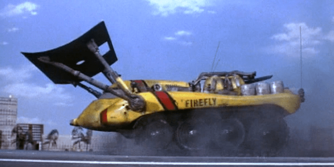
We both felt that it would look cool and would be a great match for the “most disastrous robot” competition theme. So, we went ahead.
To start with, I created the following design in Fusion 360, our go-to CAD package:

This design has plausible dimensions for a PiWars robot hull. The wheels are a diameter to suit the motors we use, there is enough room in the hull for all the necessary parts, and the tracks match the dimensions (in both thickness and width) of the Lego track parts that we use.
Nathan then created the following design, incorporating my hull “suggestion”:
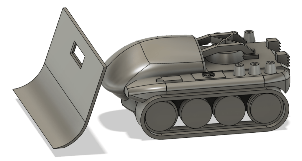
I was totally thrilled with his design. It is not easy to model parts with compound curvature, and I think he completely captured the look of the original machine. His design incorporated changes to make it suitable for the competition, for example he “blunted” the nose to make it easier to keep within the maximum length rule.
I then worked on his design in Fusion. I hollowed out the design then inserted all the parts that would be needed to make a working machine. The hull “suggestion” from earlier was replaced with a fully working hull and properly modelled track parts. Thankfully, I have 3D models of all the parts I would need, but it was still a long process.
This is the Fusion 360 model of our machine:
This diagram shows the internal components in the model:
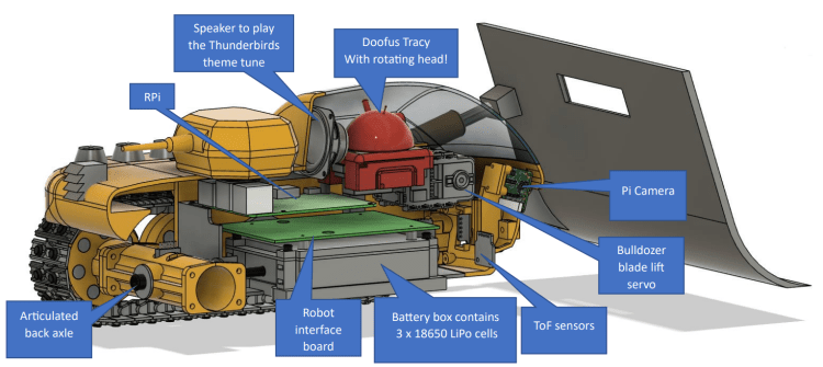
As you can see, we try to model all the parts to ensure that the whole thing will fit together correctly. Close to the competition, we removed the speaker from the back of the cab: we needed the room to install some electronics in the lid.
Robot Construction
Tracks

Firefly’s tracks are made from Lego parts. The structure element is part number 57518, the rubber treads are part 24375. We think the Lego parts are far more reliable than anything we could print.
We like our machines to have working suspension. Firefly’s suspension is a bit “experimental” because it tries to cater for tracks and mecanum wheels. Since six of the eight wheels are articulated, I expected the machine’s tracks to run off the sprockets from time to time. This appears not to be the case; even some pretty fierce driving at the Sidmouth Science Festival only exhibited this problem when the robot was allowed to drop from height and the Lego track elements unclipped.

The front sprockets are mounted rigidly to the chassis, the two middle wheels on each side are idlers (undriven) and are mounted on a rocker arm (with a lateral bearing), then the rear axle is mounted on a longitudinal bearing. When mecanum wheels are used the idlers and idler arms are not fitted. Since the rear axle is attached by a longitudinal bearing, all four mecanum wheels should remain in contact with the ground, even over uneven terrain.
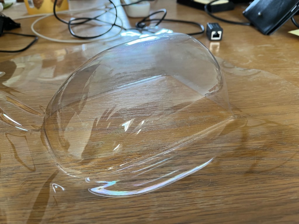
Cab Glass
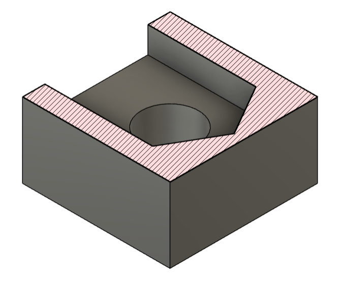
The cab “glass” was vacuum formed from 1mm thick PET-G. It was easy to create a mould in Fusion 360: a cuboid with appropriate dimensions was made, then the shape of the robot cab was subtracted from it.
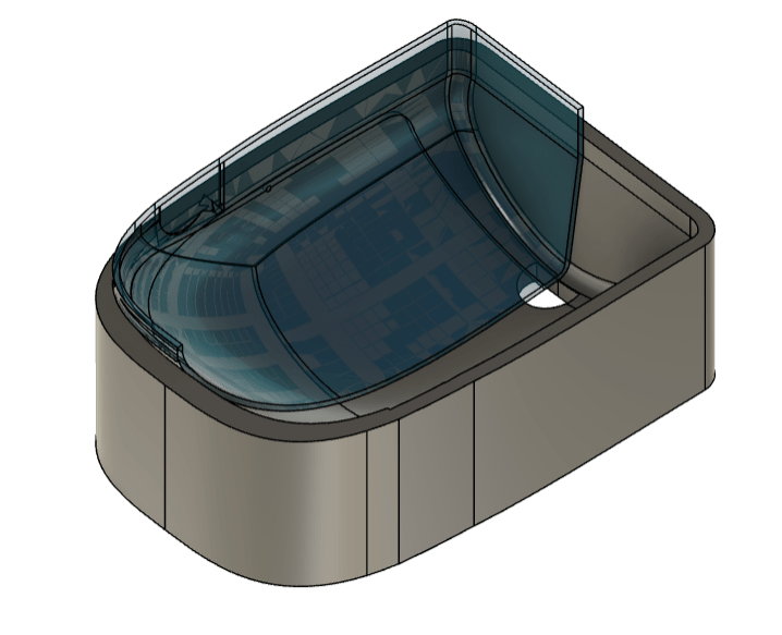
This part was then 3D printed and used to create the cab.
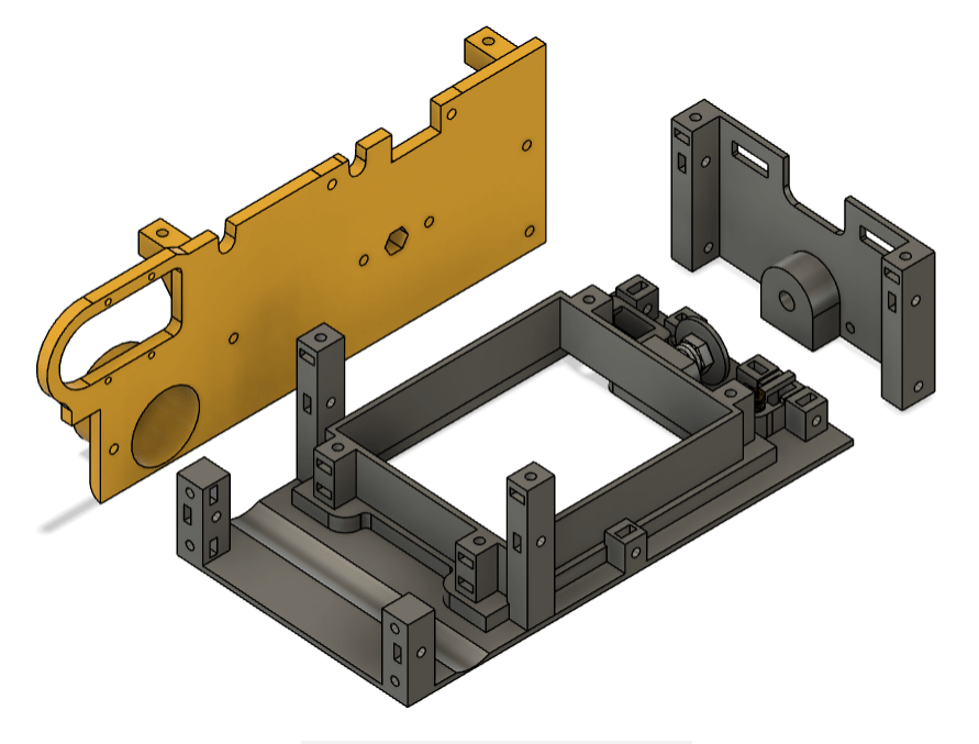
3D Printed Parts
When designing robots for printing, I used to create a hull “tub” as a single piece; this is the one from P21.

More recently, I’ve started to use bolt together hull designs. This was the technique used for PJD and for Firefly. The back and sides are basically flat panels which are typically 2mm thick. These are bolted to a base plate. On it’s own, the base plate is not particularly robust, but when the other parts are joined to it the whole is quite rigid.
I concede that a single piece hull is possibly stronger and lighter, however, I believe a hull made of several pieces has some advantages:
- Parts are flatter, so they tend to print more reliably. They can also have details on the outer face that will print nicely, normally without print supports. Single piece hulls often use lots of supports during the print process.
- Parts can be printed with an orientation that suits the application. Bear in mind that 3D prints are far stronger within layers than between layers. Earlier, I said that a single piece hull was possibly stronger, however, we have experience of single print hull tubs splitting along the print layers where the motors are attached. So far, the same has not happened on a multi-part tub. So I wonder if the multi-part hull is actually stronger due to the favourable print directions.
- A large part (such as a single piece tub) will require many hours of printing. This makes a reprint for a small design change unattractive, so manual alterations are likely. This leads to a messy build in the long run. It is more acceptable to reprint a smaller part of the build for design alterations.
- Finally, it can be easier to assemble a multi-part hull as it is easier to access the parts within the hull.
Captive Nuts
To bolt this kind of design together, I use the following “captive nut” part.
It is a cube of length 8mm with a cutout to accept an M3 nut. The cutout is just the right size so that the nut is a push fit. I have this part modelled in Fusion 360 which I can then import and absorb into components within other designs. See the image of hull parts above for some examples; the base plate for the robot includes more than 20 M3 captive nuts cubes.
I also have a similar part for M4 nuts.
Aesthetics
When I built PJD for the 2022 games, I included decorative side pieces within the tracks. These were printed in green PLA, then accent parts were painted on.
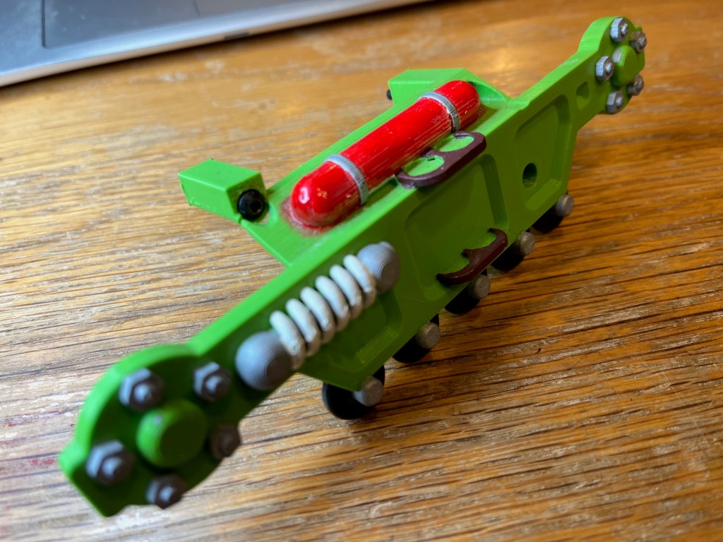
I was disappointed to find that some paints seep along the print striations; note that the red paint has spread, but the silver and white have not. Now, when I want parts to be different colours, I design and print them as separate components. Firefly’s wheels are an extreme example of this; each sprocket is made up of 11 separate pieces that press fit together.
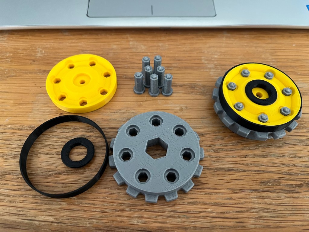
This is mainly for aesthetic reasons, but is also so that the running surfaces can be printed without supports (that tend to leave a rough surface on the component). The parts fit together snuggly; Firefly was taken to the Sidmouth Science Festival and driven around all day. I had not glued the sprockets together before going, but they only occasionally needed retightening. Now we are satisfied with the sprockets I have glued them together, ready for the competition.
Lettering
We wanted to copy the lettering on the flank of the Thunderbirds machine. I thought about decals but decided it would be too difficult to get the lettering straight and neat, bearing in mind that the surface is curved and would have visible 3D print layers. I also thought that decals would not be robust, particularly considering their location on the vehicle.
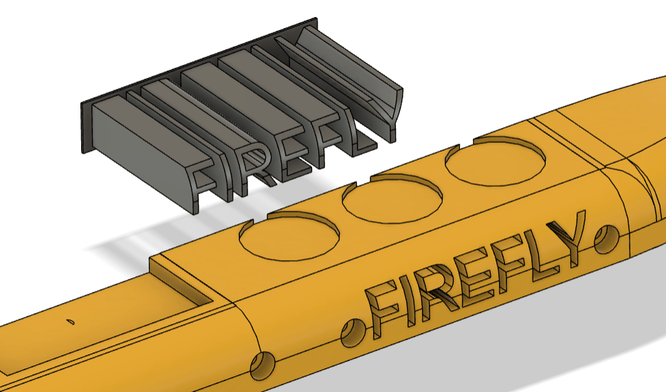
I decided to 3D print the letters. The letters are printed in black PLA, and they slide into a cutout in the side panel of the robot. A clearance of 0.1mm is designed in around every letter so that the parts fit together with minimal adjustment. I’m pleased with the results; I actually think that the lettering on our robot is a bit straighter than that on the model from the TV series!
