PCB Sent to China

Render courtesy of KiCAD’s 3D viewer

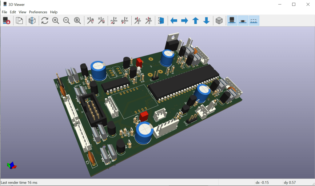
Last week I blogged that there wasn’t enough room in the robot hull for the control board. Well, I finally made it fit. I reduced the circuit a bit (I decided some of it was redundant), I used some smaller components (mainly the DC-DC converter, but also some capacitors), and I realised I could extend the board by 10mm within the existing design. I have finished the board design and sent it to JCLPCB to have it manufactured. All available digits are crossed for a positive outcome!

The board was developed in KiCAD. This is new to me, but I found it pretty easy to get the hang of. I found this video tutorial to be particularly useful.

The circuit has the following features:

  • The main controller is a Teensy 4.1 Arduino compatible. It is mounted so that it’s USB port will be exposed towards the back of the vehicle; this will make it possible to re-program it in-situ.
  • There is a JST socket which will connect to the Pi’s header. It connects the UART on the Pi to a UART in the Teensy. There are two further GPIO connections, one to indicate that the Pi is running, one to request that the Pi closes down. Power for the Pi is also provided by the connection. In operation, the Teensy combines all the robot functions which the Pi accesses via a serial protocol.
  • A LiPo protection circuit. If the LiPo voltage goes too low then this circuit can close the Pi down, then chop the power to the whole robot. The circuit expects to be connected to a 3S LiPo (which was chosen to match the AX-12 servos used).
  • Four independent 11A motor controllers for the robot drive wheels. The motors have encoders fitted, and this circuit will maintain PID control for each. This system can also be used to calibrate distances travelled.
  • An IMU (Intertial Measurement Unit). The robot uses this to understand it’s orientation in the World. It is mainly used to calibrate turns.
  • A serial connection (using the SBUS protocol) to a radio control receiver.
  • An ”implement” connector. Implements are added to the robot for some of the games. This connector presents a 3v3 serial connection and power supplies for the implements.
  • A pair of AX-12 servo bus connectors. These servos provide more torque and more control options than regular radio control servos. They are accessed via a proprietary serial protocol which the Teensy can provide via an interface on the board. The base robot uses a pair of AX-12 servos to lift the front bulldozer blade, and further servos will be used in the Eco-Disaster barrel lift.
  • An 3v3 serial interface to a further board that is mounted in the ”chin” of the robot. This board interfaces to three ToF (Time of Flight) sensors.
  • A 3v3 serial and power interface to the robot’s decorative lid. The lid will have lights and a sound system (to play the Thunderbirds theme tune). Also, the little Doofus pilot has a head turn servo.
  • A start button and a stop button interface.
  • A status LED connection.

Lets get this party started…

We’ve been accepted into PiWars 2024! So, I think it’s time for an update.

Since our last post, Firefly has jumped from the Fusion 360 CAD world into the real world. (In other words, it’s been 3D printed and sprayed). It has been fitted with a radio control system and two motors and it can now be driven.

It spent last Saturday being driven around an obstacle course (sometimes rather too enthusiastically) by people of all ages at the Sidmouth Science Festival. During the day, the tracks unclipped a few times, and the driving sprockets came undone a few times too, but basically the robot stayed in one piece for the day. The only real problem is that the paint flaked off of the cab. In my view, if it can stand being driven by random five-year-olds, then it is robust enough for PiWars, where either our expert driver, or a Raspberry Pi will be at the helm.

I was also pleased to note that the batteries (it has three 18650 LiPos wired in series giving a total capacity of 3Ah at a nominal 11.1V) were nowhere near exhausted by the end of the day.

However, there are some problems.

  • I am rather disappointed by the finish of the cab. The “glass” has picked up the layers from the 3D printed mould. Also, the paint edges are not particularly tidy, even though they were done with masking tape. Some paint mist has got inside the glass, and now (i.e. following the Science Festival) much of the paint has flaked off of the cab anyway.
  • It’s also not possible to mount the speaker in the cab, as the glass prevents access to the nuts that were meant to be used with bolts to mount the speaker.
  • But most significantly, there is not enough room in the hull for the electronics. When I did the design I planned for a robot control PCB that was roughly the same size as last year’s. I knew there would need to be extra electronics, (two extra motor drivers), but I figured I could save space by building a PCB. So far, I have not been able to get the necessary components on the PCB (without even trying to lay the board out completely).

I’m wondering if I should re-work the design to include a bigger space in the hull for a bigger PCB. And perhaps re-work the cab to make fitting the speaker easier and to remove the need to spray the vacuum formed cab. For now, no decision on the way forward has been taken.

You can find more information about Firefly here.

Hacky Racers Theme

One of the first rules of Hacky Racers reads: “It’s expected that all entries will have a theme and some decoration, to help win the crowd vote.” We decided to go with one of the original Whacky Races teams: The Ant Hill Mob. Their car was called the “Bullet Proof Bomb” and looked like this….

We did our usual approach: I press-ganged my eldest son into modelling the car in CAD, then I chopped his design until I could get it to fit onto the existing chassis. As usual, we are working on half of the design; we will mirror to create the other half at the end of the design process. This is what we have so far…

Most parts will be 3D printed, although the sides have been laser cut from ply. The parts are larger than we usually print: just the bonnet is a 49 hour print. The bumper is a plastic tube; I think it was a firework launch tube. It’s been in the I’m-sure-this-will-come-in-handy box for many years.

The box inside the car is a camera mount. It’s designed to hold a Luxonis OAK-D camera, but I think will be used with a regular Raspberry Pi camera for now. The box has a clear acrylic screen to protect the camera, although this doesn’t show on the image. The organisers have pointed out that the race will take place, even if it is raining.

The cup in the roof of the car is to hold the Hacky Racers transponder.

As I write this, the 3D printer is running. And there’s software to get working.

Hacky Racer progress

The car hardware is now largely complete, so I thought I’d share a couple of images.

The construction has 3 decks.

  • The lowest has a Raspberry Pi with power supply which connects to the front facing camera. For now, this is just collecting video data. In future, I would like the vehicle to be guided by this system, although I might replace the RPi with a Jetson Nano for that.
  • The second deck has a ESP32 and RTK GNSS system. The ESP32 receives RTCM data from a laptop via an ESP-Now based link. The same link is used by the car to send telemetry data to the base station.
    The ESP32 also listens to an R/C receiver. It decodes three channels: throttle, steering and a three position switch. The switch selects the mode: record (the car can be manually driven around the track with the R/C controller in this mode. As it does this, the car records a GNSS “bread-crumb” trail), stop, and autonomous (where the car follows the previously defined trail).
  • The top layer holds the GNSS antenna. The antenna sits above a foil ground plane.

Following a conversation with DonK, I plan to make it possible to adjust the height of the camera above the track. It is currently set to 120mm, but Don has suggested that 300mm is a better position. It would be nice to be able to capture data at several heights in order to compare the performance of the lane following system for different settings.

Hacky Racers

Hacky Racers is only two months away. Its time to get to work…

This is the chassis we plan to use. We’ve had it for years, and it’s a bit worn out / damaged / bent, but I think / hope it will be fine for the competition. It has some nice features: it’s four wheel drive, it has independent suspension with dampers, and the motor controller is a separate device to the RC receiver. At approximately 420mm long by 310mm wide it easily fits into the A2 sized rules, but there’s still plenty of room to add the necessary electronics.

It has a brushed motor, but it’s still very quick. I’m sure we will not be driving it at full speed in autonomous mode!

We plan to add a deck on top of the machine, between the axles, to carry the new electronics for autonomous guidance. We plan to use an RTK GNS module to control the vehicle autonomously to begin with. We hope to add a camera to the front which we will use to capture video during races in July. This will then be used to train an AI system for guidance in the future (hopefully).

The first job is to add the deck on top of the vehicle to carry the new electronics.

Shepherds Pi Update

Earlier in the month I said we were dropping Shepherds Pi in favour of the other autonomous games.  Things have moved on since then…

To start with, we finished videos of the other two autonomous games that could be submitted.  I think we will probably attempt new videos of both; we can certainly get them slicker, but I’m happy for now.  This made Shepherds Pi the new priority.

Secondly, I re-tuned the robot motor control PIDs and dead reckoning system.  I think the tuning required for tracks is not the same as the tuning that was carried through from last year’s (wheeled) robot.  The robot now moves about the arena more accurately.

I added several coloured discs around the arena to provide additional localisation opportunities during the game, see below.

This image has an empty alt attribute; its file name is targets1.png

The “sky” on the sheep decorations was removed; this had been the original localisation target for the robot but was rather error prone.  A yellow band was added which is a more robust target. 

Originally, the pen was made from Lego train track pieces connected to 3D printed supports. However, these were about 10mm longer than required which made the entrance to the pen about 20mm too narrow. That 20mm was proving to be important, but I couldn’t bring myself to cut the tracks down. Instead I designed and printed some new pen walls; they were made to look suitably aged to fit with the “Old McDoofus” theme. Actually, they are derived from the trough planks I made for “Feed the Cattle”.

The original Lego pen fence.
The new 3D printed, regulation-length fence.

We now have a video of Shepherd’s Pi being performed autonomously, although we are not even close to being able to perform the target three rounds.

The next step is to re-film the challenge with the whistle detector installed.